SOLID architecture principles in C# by examples

SOLID principles are design principles that help to create robust, scalable and maintainable software architecture. SOLID is an acronym which stands for:

  • S – SRP (Single responsibility principle)
  • O – OCP (Open closed principle)
  • L – LSP (Liskov substitution principle)
  • I – ISP ( Interface segregation principle)
  • D – DIP ( Dependency inversion principle)

In the following sections I will describe all the principles by examples starting from one demo and upgrading this demo with the principles applyied.

  1. Reduce tight coupling
  2. Increase readability, extensibility and maintenance
  3. Achieve reduction in complexity of code
  4. Reduce error and implement Reusability
  5. Achieve Better testability of code

S – SRP (Single responsibility principle)

SRP principle says that every module/class should have only one responsibility and not multiply. Consider this class:

public class Customer
{
    public void Register(string email, string password)
    {
        try
        {
             //code for registering user

             if (ValidEmail(email))
             {
                 SendEmail(email, "Email title", "Email body");
             }
         }
         catch(Exception ex)
         {
             //log if error occurs
             throw;
         }
      }

     public bool ValidEmail(string email)
     {
         return email.Contains("@");
     }

     public void SendEmail(string mail, string emailTitle, string emailBody)
     {
         //send email
         Console.WriteLine(string.Format("Mail:{0}, Title:{1}, Body:{2}", mail, emailTitle, emailBody));
     }
 }

Following this principle, the responsibility of the Customer class should be only the Register method. ValidEmail and SendEmail should not be defined in the same class. The Customer class should not worry with the definition of Validation Rules of the Email address and sending messages.

Following the SRP principle, the code should look like in the following way:

public class Customer
{
    public void Register(string email, string password)
    {
        try
        {
            //code for registering user
            var mailService = new MailService();

            if (mailService.ValidEmail(email))
            {
                  mailService.SendEmail(email, "Email Title", "Email Body");
            }
         }
         catch (Exception ex)
         {
               //log if error occurs
                throw;
          }
      }
 }
public class MailService
{
    public bool ValidEmail(string email)
    {
        return email.Contains("@");
    }

    public void SendEmail(string mail, string emailTitle, string emailBody)
    {
        //send email
        Console.WriteLine(string.Format("Mail:{0}, Title:{1}, Body:{2}", mail, emailTitle, emailBody));
    }
 }

Now the functionality for Email Validation and Sending can be delegated to the MailService class.

O – OCP (Open closed principle)

OCP principle says that every module/class is open for extension and closed for modification. Consider the previous class with the SRP principle applied. Let’s say that we want to add additional functionality.After user registration and sending email we want to send sms to that user. According to the SRP principle we would add additional class for SMS as follows:

public class SmsService
{
    public void SendSms(string number, string smsText)
    {
        //send sms

        Console.WriteLine(string.Format("Number:{0}, Message:{1}", number, smsText));
     }
}

After this the Customer class would be extended in the following way:

public class Customer
{
    public void Register(string email, string password)
    {
        try
        {
              //code for user registration

              var mailService = new MailService();
              var smsService = new SmsService();

              if (mailService.ValidEmail(email))
              {
                    mailService.SendEmail("test@test.com", "User registration", "Body of message...");
              }

              smsService.SendSms("111 111 111", "User succesfully registered...");
          }
          catch (Exception ex)
          {
              //log if error occurs

              throw;
           }
     }
}

As we saw we have extended the Customer class for sending different types of notifications which is against OCP rules. In order to follow the OCP principle and not the break the SRP principle we should isolate the sending of the notifications (email and sms) in a more generic way.

public abstract class NotificationService
{
    public abstract void SendNotification();
}
public class MailService:NotificationService
{
    public string Email { get; set; }
    public string EmailTitle { get; set; }
    public string EmailBody { get; set; }

    public bool ValidEmail()
    {
        return Email.Contains("@");
    }

     public override void SendNotification()
     {
          //send email

          Console.WriteLine(string.Format("Mail:{0}, Title:{1}, Body:{2}", Email, EmailTitle, EmailBody));
      }
}
public class SmsService:NotificationService
 {
        public string Number { get; set; }
        public string SmsText { get; set; }

         public override void SendNotification()
         {
                //send sms

                 Console.WriteLine(string.Format("Number:{0}, Message:{1}", Number, SmsText));
          }
 }
public class Customer
 {
      public void Register(string email, string password)
      {
            try
            {
                    //kod za registracija na korisnik

                     var mailService = new MailService();
                     mailService.Email = email;
                     mailService.EmailTitle = "User registration";
                     mailService.EmailBody = "Body of message...";

                    if (mailService.ValidEmail())
                    {
                               mailService.SendNotification();
                    }

                    var smsService = new SmsService();
                    smsService.Number = "111 111 111";
                    smsService.SmsText = "User succesfully registered...";

                     smsService.SendNotification();
             }
             catch (Exception ex)
             {
                      //log if error occurs

                       throw;
              }
      }
 }

As we can see we isolate the sending of email and sms as a component.

L – LSP (Liskov substitution principle)

LSP principle says that the parent object should easily replace the child object. Let me explain this principle by example. This principle is just an extension of the OCP and it means that we must ensure that new derived classes extend the base classes without changing their behavior. Consider the previous example with the SRP and OCP principles applied. Let’s say that we want to add additional functionality to the NotificationService class for writing notification records to Database but this records to be only for emails.

public abstract class NotificationService
{
    public abstract void SendNotification();
    public abstract void AddNotificationToDB();
}
public class MailService:NotificationService
{
    public string Email { get; set; }
    public string EmailTitle { get; set; }
    public string EmailBody { get; set; }

    public bool ValidEmail()
    {
        return Email.Contains("@");
    }

    public override void SendNotification()
    {
         //send email

         Console.WriteLine(string.Format("Mail:{0}, Title:{1}, Body:{2}", Email, EmailTitle, EmailBody));
     }

     public override void AddNotificationToDB()
     {
        //add to database
     }
}
public class SmsService:NotificationService
{
     public string Number { get; set; }
     public string SmsText { get; set; }

     public override void SendNotification()
     {
        //send sms

        Console.WriteLine(string.Format("Number:{0}, Message:{1}", Number, SmsText));
      }

      public override void AddNotificationToDB()
      {
          throw new Exception("Not allowed");
      }
}
public class Customer
{
   public void Register(string email, string password)
   {
      try
     {
        //kod za registracija na korisnik

        var mailService = new MailService();
        mailService.Email = email;
        mailService.EmailTitle = "User registration";
        mailService.EmailBody = "Body of message...";

        if (mailService.ValidEmail())
        {
             mailService.SendNotification();
             mailService.AddNotificationToDB();
        }

        var smsService = new SmsService();
        smsService.Number = "111 111 111";
        smsService.SmsText = "User succesfully registered...";

        smsService.SendNotification();
        smsService.AddNotificationToDB();
    }
    catch (Exception ex)
    {
        //log if error occurs

        throw;
     }
   }
 }

Above code in the Customer class will fail because of the AddNotificationToDB method in the smsService class called. One solution is not to call the above method but we raise another problem. We have a class that implements method that is not used. We will fix this issue if we implement in the following way:

public interface INotification
{
    void SendNotification();
}
 public interface INotificationToDB
 {
    void AddNotificationToDB();
 }
public class MailService:INotification,INotificationToDB
{
      //all the required code
}
public class SmsService: INotification
{
    //all the required code
}

I – ISP ( Interface segregation principle)

The ISP says that clients should not be forced to implement interfaces they don’t use. According to the previous principles let’s say that we want to add additional functionality to the Notification interface for Reading notification from Database.

public interface INotificationToDB
{
   void AddNotificationToDB();
   void ReadNotification();
}

With this definition we obligate the class that inherits from this interface to implement the method for reading notification. Maybe in some cases we don’t want to have this but because of the inheritance we need to define the method in the class even if we don’t want to implement this. The solution for this problem is to separate all the methods that are not used everywhere in a separate interface like as follows:

public interface INotificationToDB
{
     void AddNotificationToDB();
}
public interface INotificationToDBRead
{
     void ReadNotification();
}
public interface INotification
{
    void SendNotification();
}
 public class MailService:INotification,INotificationToDB,INotificationToDBRead
 {
    //implemented code
 }
public class SmsService: INotification
{
   //implemented code
}

D – DIP ( Dependency inversion principle)

DIP says that high-level modules/classes should not depend upon low-level modules/classes. Both should depend upon abstractions. Secondly, abstractions should not depend upon details. Details should depend upon abstractions. Let’s explain this principle by example. From the previous principles we had the following situations with the Customer class:

public class Customer
{
    public void Register(string email, string password)
    {
         try
         {
              //kod za registracija na korisnik

              var mailService = new MailService();
              mailService.Email = email;
              mailService.EmailTitle = "User registration";
              mailService.EmailBody = "Body of message...";

              if (mailService.ValidEmail())
              {
                  mailService.SendNotification();
                  mailService.AddNotificationToDB();
              }

              var smsService = new SmsService();
              smsService.Number = "111 111 111";
              smsService.SmsText = "User succesfully registered...";

              smsService.SendNotification();
           }
           catch (Exception ex)
           {
              //log if error occurs

              throw;
            }
      }
}

We have a lot of code here. Let’s isolate this class as a separate component.

public class Customer
{

      private INotification notification;

      public Customer(INotification n)
      {
          notification = n;
      }

      public void Register(string email, string password)
      {
          try
          {
               //kod za registracija na korisnik

           }
           catch (Exception ex)
           {
               //log if error occurs

                throw;
            }
       }

       public void SendNotification(INotification notification)
       {
           notification.SendNotification();
       }
 }

Having the architecture with all the principles applied we can call the Customer class from outside.

class Program
{
    static void Main(string[] args)
    {
       var service = new MailService();
       service.Email = "test@test.com";
       service.EmailTitle = "User registration";
       service.EmailBody = "Body of message...";

       if (service.ValidEmail())
       {
           var customer = new Customer(service);

           customer.Register("test@test.com", "password");
           customer.SendNotification(service);

           service.AddNotificationToDB();
        }

        var smsService = new SmsService();
        smsService.Number = "111 111 111";
        smsService.SmsText = "User succesfully registered...";

        var customer1 = new Customer(smsService);
        customer1.SendNotification(smsService);

        Console.ReadLine();
   }
}

As we saw, we have a total isolation and every functionality is represented as a component. Everything is abstracted, clear, easy for testing and most of all scalable, maintainable and usable.

Final remarks

We have gone throw all the principles for building scalable, maintainable and robust software architecture.

The code for implementing this principles is much longer than ordinary code but in long term you will have a big business value for the entire solution. You don’t have to follow all this principles 100% but it is a good practice if you want professional, easy readable and maintainable applications.

C# Generics vs C++ Templates

C# Generics and C++ Templates provide support for parameterized types. The following are the differences −

Flexibility

C++ Templates are more flexible than C# Generics

Explicit specialization

Explicit specialization is not supported by C#

Type Parameter

The type parameter cannot be used as the base class for the generic type in C#

C# does not allow type parameters to have default types.

Run-Time

The C++ template has a compile-time modal, whereas C# Generics is both compile and run-time. Generics have run-time support.

Non-type template parameters

C#Templates will not allow non-type template parameters.

Partial Specialization

C# does not even support partial specialization.

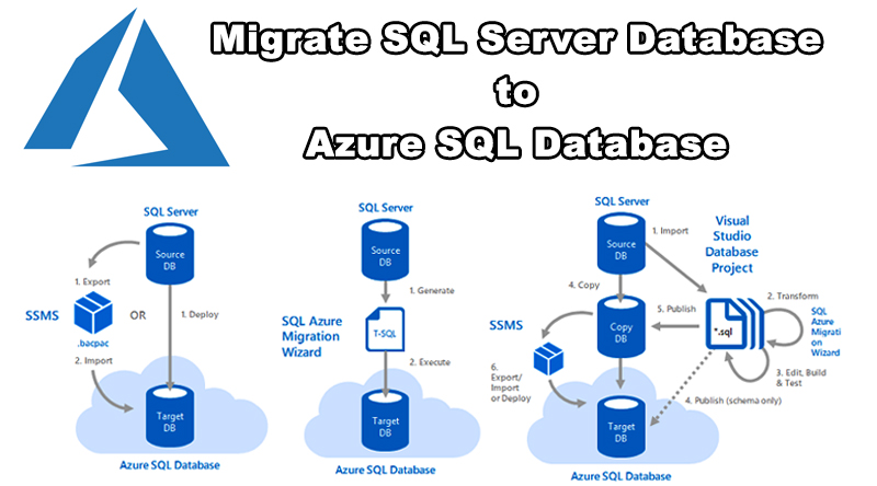
Step by Step How to Migrate SQL Server Database to Azure SQL Database in Microsoft Azure

Introduction

The Microsoft SQL Server migrate both your schema and your data from the SQL Server database in your current environment into SQL Database, provided the existing database passes compatibility tests.

Data Migration Assistant to Moving your SQL Server database to an Azure SQL Database single database is as simple as creating an empty SQL database in Azure and then using the Data Migration Assistant (DMA) to import the database into Azure.

Prerequisites

  • SQL Server Management Studio (SSMS)
  • Data Migration Assistant (DMA)

SQL Server Migration Assistant Supported Sources and Target Versions

  • SQL Server 2008
  • SQL Server 2008 R2
  • SQL Server 2012
  • SQL Server 2014
  • SQL Server 2016
  • Azure SQL Database
  • SQL Server 2017 on Windows and Linux
  • Azure SQL Data Warehouse

Installed the newest version of the Data Migration Assistant (DMA).

R with PowerBI – A step by step guide approach

A lot of interests are visible everywhere how to integrate R scripts with Microsoft PowerBI dashboards. Here goes a step by step guidance on this.

Lets assume, you have some couple of readymade R code available, for example , with ggplot2 library. Lets find the following scripts performing analytics using CHOL data.

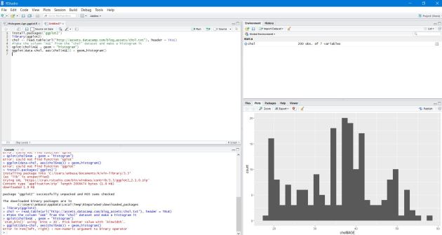
  1. Open R studio or R Package (CRAN) & install ggplot2 library first.
  2. Paste the following R script & execute it.

install.packages(‘ggplot2’)
library(ggplot2)
chol <- read.table(url(“http://assets.datacamp.com/blog_assets/chol.txt&#8221;), header = TRUE)
#Take the column “AGE” from the “chol” dataset and make a histogram it
qplot(chol$AGE , geom = “histogram”)
ggplot(data-chol, aes(chol$AGE)) + geom_histogram()

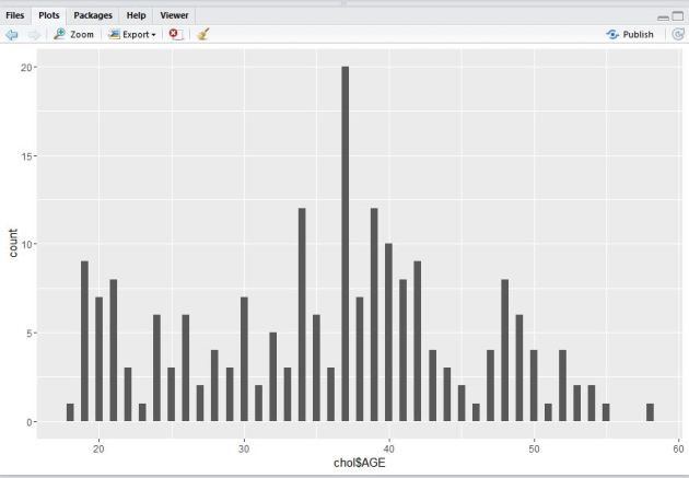
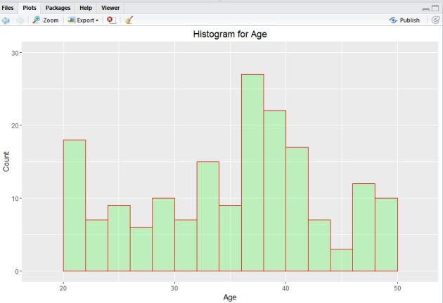
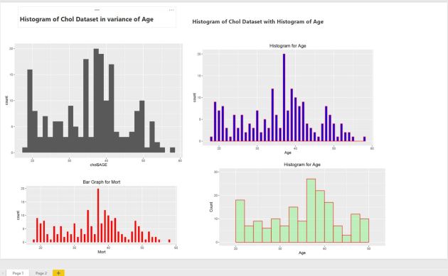
you should be able to see the visuals output like this.

3. Next, execute the following pieces of R code to find out the binwidth argument using ‘qplot()‘ function.

qplot(chol$AGE,
geom = “histogram”,
binwidth = 0.5)

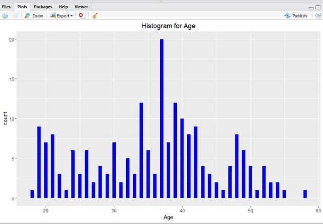
4. Lets take help of hist() function in R.

#Lets take help from hist() function
qplot(chol$AGE,
geom=”histogram”,
binwidth = 0.5,
main = “Histogram for Age”,
xlab = “Age”,
fill=I(“blue”))

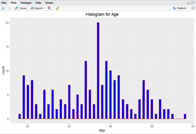
5. Now, add I() function where nested  color.

#Add col argument, I() function where nested color.
qplot(chol$AGE,
geom=”histogram”,
binwidth = 0.5,
main = “Histogram for Age”,
xlab = “Age”,
fill=I(“blue”),
col=I(“red”))

6. Next, adjust ggplot2 little by the following code.

#Adjusting ggplot
ggplot(data=chol, aes(chol$AGE)) +
geom_histogram(breaks=seq(20, 50, by = 2),
col=”red”,
fill=”green”,
alpha = .2) +
labs(title=”Histogram for Age”) +
labs(x=”Age”, y=”Count”) +
xlim(c(18,52)) +
ylim(c(0,30))

7. Plot a bar graph with this following code.

#Plotting Bar Graph
qplot(chol$AGE,
geom=”bar”,
binwidth = 0.5,
main = “Bar Graph for Mort”,
xlab = “Mort”,
fill=I(“Red”))

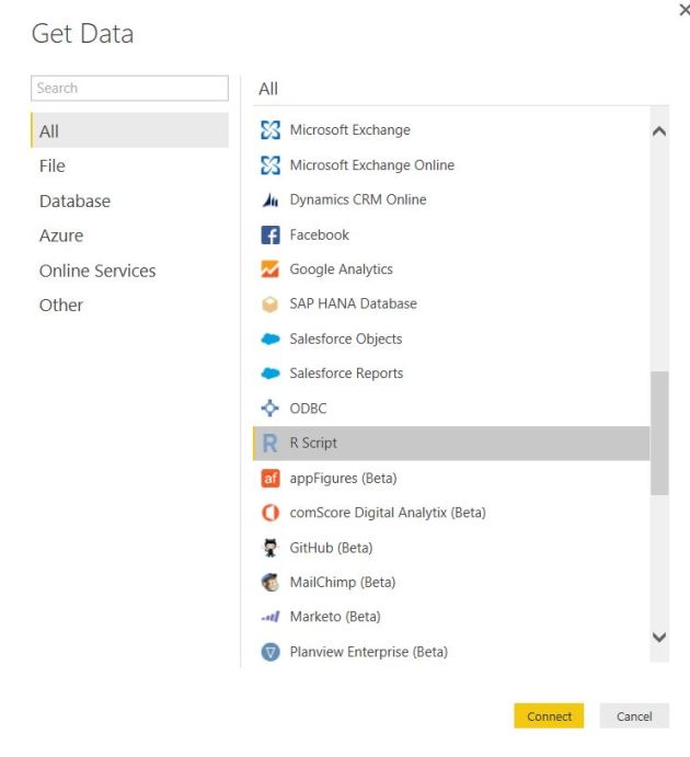
8. Next, open PowerBI desktop tool. You can download it free from this link. Now, click on Get Data tab to start exploring & connect with R dataset. 

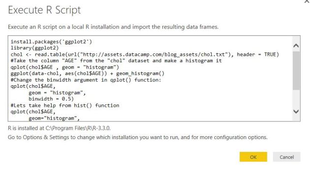
If you already have R installed in the same system building PowerBI visuals , you just need to paste the R scripts next in the code pen otherwise , you need to install R in the system where you are using the PowerBI desktop like this.

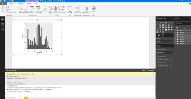
9. Next, you can also choose the ‘custom R visual’ in PowerBI desktop visualizations & provide the required R scripts to build visuals & finally click ‘Run’.

10. Build all the R function visuals by following the same steps & finally save the dashboard.

11.You can refresh an R script in Power BI Desktop. When you refresh an R script, Power BI Desktop runs the R script again in the Power BI Desktop environment.

Azure – Using Powershell

Introduction

 In this article, I am going to show how to set up resources to work with Azure using power shell. We will learn basic power shell commands which are required to work with Azure. This article can be used by beginners, intermediates, and professionals. 

Prerequisite

  • Azure subscription
  • Windows Power shell version 5.1.1

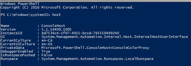
First, we will check which version of Powershell has been installed in your machine using the below command CommandHost

 If you don’t have version 5.1.1 in your machine, it means you don’t have Windows Management Framework 5.1 installed in your machine. You can download and install the correct version from the below URL. Please select the correct version as per the operating system from the below URL. https://www.microsoft.com/en-us/download/details.aspx?id=54616 Also, we should have a NuGet installed on the machine. The below command can be used to install Nuget if not installed CommandInstall-PackageProvider -Name Nuget -RequiredVersion 2.8.5.201 – force

Tools

 We can connect and use Azure in various ways using various tools. To work with Microsoft Azure it’s better to know all these tools. Few of these tools are,

  1. Azure Portal
  2. Windows Power shell
  3. Azure Command Line Interface (CLI)
  4. Azure cloud shell – This allowed you to use both Bash and power shell from inside Azure portal.

Here I am going to show, how to connect and use Azure with Window Power shell commands. 

How to connect Azure using Powershell?

 Below are the steps we need  to follow to work with a power shell command,

  • Open Window Power shell command line as administrator.
  • First, we need to set execution policies so we can go and install remotely signed packages.

CommandSet-ExecutionPolicy RemoteSigned

  • Once the above settings will be done, we will install all Azure modules required for the current users using the below command.

CommandInstall-Module -Name Az -AllowClobber -Scope CurrentUser

  • Once Azure modules are installed, we need to import Az to work with Azure command. Please note that ‘Az’ is used for Azure. 

CommandImport-Module Az verbose 

  • Once modules are imported, we will try to connect the Azure account. Execute the below command.

CommandConnect-AzAccount

 Once you’ve logged in with credentials you will see the below image with subscription details like Account, SunscriptionName, TenantId, and Environment. 

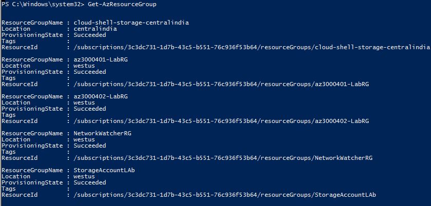
 Let’s try to get all resources available with our account. CommandGet-AzResourceGroup

 Now we will create a new resource group and then check again using commands. CommandNew-AzResourceGroup -Name RG01 -Location “South Central US” 

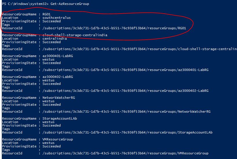
 Let’s try to get all resource groups again to check if the new resource group is created or not. CommandGet-AzResourceGroup

 You can see in the above image that newly created resource groups have been created. We can execute and achieve any thing using power shell commands. It’s not possible to cover all commands in a single article

Azure IoT Solution Architecture Best Practices – IoT Devices Provisioning

In the modern IoT Solutions often we have a big number of devices, connected to the back end: thousands hundred thousands or even millions of devices.
All these devices should have initial configuration and to be successfully connected to the back-end and this configuration should be done automatically.

In a sequence of article there will be described the main concepts of automatic provisioning and best practices how to implement it (focusing more on Azure based IoT solutions).

Challenges:

If devices are configured in advance during the manufacturing it will be:

1. very difficult to know in advance the connection settings during the manufacturing. For big solutions it is possible to know the customer, but it is difficult to know details about exact connection in advance.

2. Setting the connection in advance is not secure. This approach will give options if somebody know the settings to initiate connection from a fake device and to compromise the system.

3. In the modern IoT solutions it is recommended to have implemented MFA (multi factor authentication). 

To be possible to have zero touch provisioning is needed to have pre-set of the devices from the back-end.

This initial configuration includes 2 groups of settings:

  • Settings, related to the exact connection of the devices to the back-and : end point and authentication
  • Settings, related to the specific IoT Solution business logic as logical grouping of the devices, which could be done from the back-end 

The first group of settings needs communication between back-end and devices to let them know it’s connection and to provide authentication.

How is possible devices to have automated configuration? The most common approach is to have a common “discovery” service for the whole solution.
This service will not be changed and devices will connect to this service to receive its settings.

To provide MFA for device registration information on manufactured devices with their specific properties should be imported in advance in the system. This import should be based on the information, provided from the device’s manufacturer. It will be not possible somebody non-authenticated from outside to provide this production data import.

Authentication of devices for initial provision should be provided using 2 independent channels (MFA). Usually those c channels are:

  • Import of the manufactured device data
  • Authentication of devices to establish communication channel, used for provisioning

Authentication of devices to establish connection for initial  provisioning can be done in several ways:

  • Basic authentication (not recommended)
  • Integrated authentication using identity management system like Microsoft Active Directory
  • Secure attestation using .X.509 or TPM-based identities

Using authentication with specific credentials brings more complexity and more risk. Most of the modern IoT solutions are designed to use secured connection, based on certificates in different varieties. 

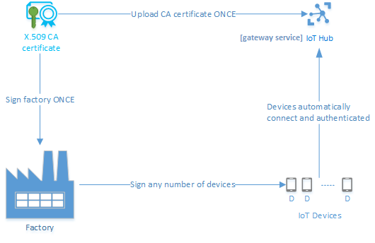
The both parts of the authentication are 2 sequential parts of the provisioning process.

  • Manufacturing step.
  • Solution setup step (back-end setup and device initiated provisioning).

Fig.1 Provisioning based on manufactured devices data and certificates.

Manufacturing step contains:

  • Base software install and setup.
  • Configuring pre-requisites for device provisioning: global endpoint, certificate etc.

The back-end setup includes:

  • Importing information about devices to the back-end system.
  • Integration with PKI (importing of public certificates in the IoT Solution) – when certificate based security is implemented
  • Integration with identity management system – when authentication is based on this approach.
  • Configuring an appropriate discovery service (IoT Hub Device Provisioning Service in Azure), which is able to assist during the provisioning and when device is authenticated to sent the settings to the correct gateway service (IoT Hub).

When the back-end configuration is done it is possible to start the provisioning process, initiated from the device.

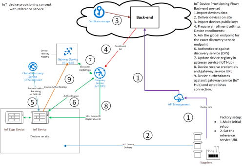
Fig.2 describes detailed the common approach for modern zero-touch device provisioning.

Fig.2 IoT provisioning concept.

Configuring Active Directory Domain Services in Azure Cloud

The first question that people might have after looking at the title of this blog post is: “Why would I need to configure AD Services in Azure if it already offers a managed service?” I was thinking the same thing when I ended up configuring AD services on my VMs in Azure. The reason I had to do that rather than using the managed service was that I needed an active directory domain for a small environment I was spinning up for test/dev purposes. I didn’t need the multi-tenancy and other features that Azure AD offered. If you think that you might be in the same boat, then read along and see the step by step instructions on how to configure AD on VMs running on Azure Cloud.

  1. Select the Azure region that you want to use to spin up your instances and then create a new virtual network. In my case, I am using the US Central region and I created a virtual network with the address space of 10.1.0.0/16.
  2. Create a new Availability Set for your AD VMs. This step is optional, but it helps to have an availability set to ensure that the two AD servers that you spin up aren’t going to run on the same underlying hardware. You can keep the default settings for the Failure domains and Update domains when you are creating the availability set.
  3. Create two subnets inside the virtual network that you created. One of the subnets can be a public subnet with access to the internet and the other one can be a private subnet. I used the private subnet to host my AD VMs as I didn’t need those VMs to be accessed from my laptop.
  4. Create and configure network security groups(NSGs) for the two subnets that you created. For the public subnet, I created inbound rules allowing HTTPS and RDP traffic and blocking all the other traffic from the outside world. I added another rule to allow all traffic from the private subnet. Since NSGs are stateful, I didn’t have to create matching outbound rules. For the private subnet, I created a rule to allow all traffic from my public subnet and block all the traffic from anywhere else. NSGs evaluate rules in an ascending order, so make sure to assign a lower numerical value to allow rules as compared to the deny rules. As a best practice, you should leave enough space between these rules, so that you can create additional rules in the future if needed.
  5. Next step will be to deploy virtual machines in the private subnet that we created. In the VM creation wizard, make sure that you select the correct virtual network, subnet, and NSG. Also, make sure that you don’t attach a public IP address to the VM. I used the Windows Server 2016 Datacenter image and chose DS1 v2 as my instance type. You can go for a different image type and size depending on your needs.
  6. Once the VMs are up and running, we need to change the IP settings, so that the AD servers have static IP addresses. You can use the following AzureRM powershell cmdlets:$nic=Get-AzureRmNetworkInterface -Name TestNIC -ResourceGroupName TestRG $nic.IpConfigurations[0].PrivateIpAllocationMethod =”Static” $nic.IpConfigurations[0].PrivateIpAddress =”10.1.1.6″ Set-AzureRmNetworkInterface -NetworkInterface $nic Get-AzureRmNetworkInterface -Name TestNIC -ResourceGroupName Test
  7. Or, you can also use the Azure GUI to set static IPs on the AD VMs. Navigate to the VM, click Network Interfaces, Click on the interface that you want to modify, Click on IP configuration, Click on the IP and then select Static under Assignment and click Save. If you are assigning a different IP than what was already assigned to the virtual machine, you will have to restart the VM for it to get the new IP address.
  8. Now that you have configured static IP addresses for the AD VMs, RDP into the primary AD VM using a jumphost or a bastion host.
  9. Install the Active Directory Domain Services role on the primary AD VM. Once the role is installed, next step is to complete the post configuration where we will create a new forest. This wizard is the same wizard that you use when you create a new forest in your private cloud.
  10. Once the AD role is installed and configured on the primary VM, then the next thing we need to do is to modify the DNS servers that would be used by the VMs in your virtual network. You can do this through the GUI by navigating to the virtual network, and select DNS servers. Change the setting from Default (Azure provided) to Custom, and enter the IP address of the first AD Server that you configured in the previous step.
  11. Once the DNS server is configured, RDP into the second AD VM that you created earlier and install the Active Directory Domain Services role. This time during the post configuration wizard, select “Add a domain controller to an existing domain”. Again this wizard is identical to how you would add a secondary domain controller in your own datacenter.
  12. Once you have configured the second AD VM, go back to the DNS server setting for your virtual network and add an entry for the second AD VM.

That’s it, you are done. Now all the Virtual machines that you spin up in your virtual network will automatically use the AD VMs as the DNS servers and you can join them to the new domain in the same way that you would in the case of your own datacenter. Please use this setup only for test/dev purposes because these VMs won’t offer you the same level of availability as the Azure AD service.

Control IoT Devices Using Scala on Databricks (Based on ML Model Output)

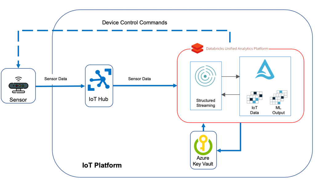
Today I would like to talk about how we can build a serverless solution on Azure that would take us one step closer to powering industrial machines with AI, using the same technology stack that is typically used to deliver IoT analytics use cases. I demoed a solution that received data from an IoT device, in this case a crane, compared the data with the result of a machine learning model that has ran and written its predictions to a repository, in this case a CSV file, and then decided if any actions needs to be taken on the machine, e.g. slowing the crane down if the wind picks up. My solution had 3 main components:

  1- IoT Hub: The gateway to cloud, where IoT devices connect and send data to

 2- Databricks: The brain of the solution where the data received from IoT device is compared with what the ML algorithm has predicted, and then decided if to take any actions

  3- Azure Functions: A Java function was deployed to Azure Functions to call a Direct Method on my simulated crane and instruct it to slow down. Direct Method, or device method, provide the ability to control the behaviour of IoT devices from the cloud.

Since then, I upgraded my solution by moving the part responsible for sending direct methods to IoT devices from Azure Functions into Databricks, as I promised at the end of my talk. Doing this has a few advantages:

  • The solution will be more efficient since the data received from IoT devices hops one less step before the command is sent back and there are no delays caused by Azure Functions.
  • The solution will be more simplified, since there are less components deployed in it to get the job done. The less the components and services in a solution, the lower the complexity of managing and running it
  • The solution will be cheaper. We won’t be paying for Azure Functions calls, which could be pretty considerable amount of money when there are millions of devices connecting to cloud

This is what the solution I will go through in this post looks like:

I must mention here that I am not going to store the incoming sensor data as part of this blog post, but I would recommend to do so in Delta tables if you’re looking for a performant and modern storage solution.

Azure IoT Hub

IoT Hub is the gateway to our cloud-based solution. Devices connect to IoT Hub and start sending their data across. I explained what needs to be done to set up IoT Hub and register IoT devices with it in my previous post. I just upgraded “SimulatedDevice.java” to resemble my simulated crane and send additional metrics to cloud: “device_id”, “temperature”,”humidity”,”height”,”device_time”,”latitude”,”longitude”,”wind_speed”,”load_weight” and”lift_angle”. Most of these metrics will be used in my solution in one way or another. A sample record sent by the simulated crane looks like below:
Machine Learning

Those who know me are aware that I’m not a data scientist of any sort. I understand and appreciate most of the machine learning algorithms and the beautiful mathematical formulas behind them, but what I’m more interested in is how we can enable using those models and apply them to our day to day lives to solve problems in form of industry use cases.

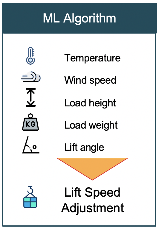
For the purpose of this blog post, I assumed that there was an ML model that has ran and made its predictions on how much the crane needs to slow down based on what is happening in the field in terms of metrics sent by sensors installed on the crane:

This is how the sample output from our assumed ML model looks like:

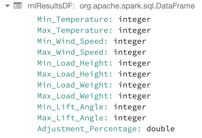
As an example to clarify what this output means, let’s look at the first row. It specifies if temperature is between 0 and 10 degrees of celsius, and wind speed is between 0 and 5 km/h, and load height is between 15 and 20 meters, and load weight is between 0 and 2 tons, and load lift angle was between 0 and 5 degrees, then the crane needs to slow down by 5 percent. Let’s see how we can use this result set and take actions on our crane based on the data we receive in real time.

Azure Key Vault

There are a couple of different connection strings that we need for our solution to work, such as “IoT Hub event hub-compatible” and “service policy” connection strings. When building production grade solutions, it’s important to store sensitive information such as connection strings in a secure way. I will show how we can use plain-text connection string as well as accessing one stored in Azure Key Vault in the following sections of this post.

Our solution needs a way of connecting to the IoT Hub to invoke direct methods on IoT devices. For that, we need to get the connection string associated with Service policy of the IoT Hub using the following Azure cli command:

az iot hub show-connection-string --policy-name service --name <IOT_HUB_NAME> --output table

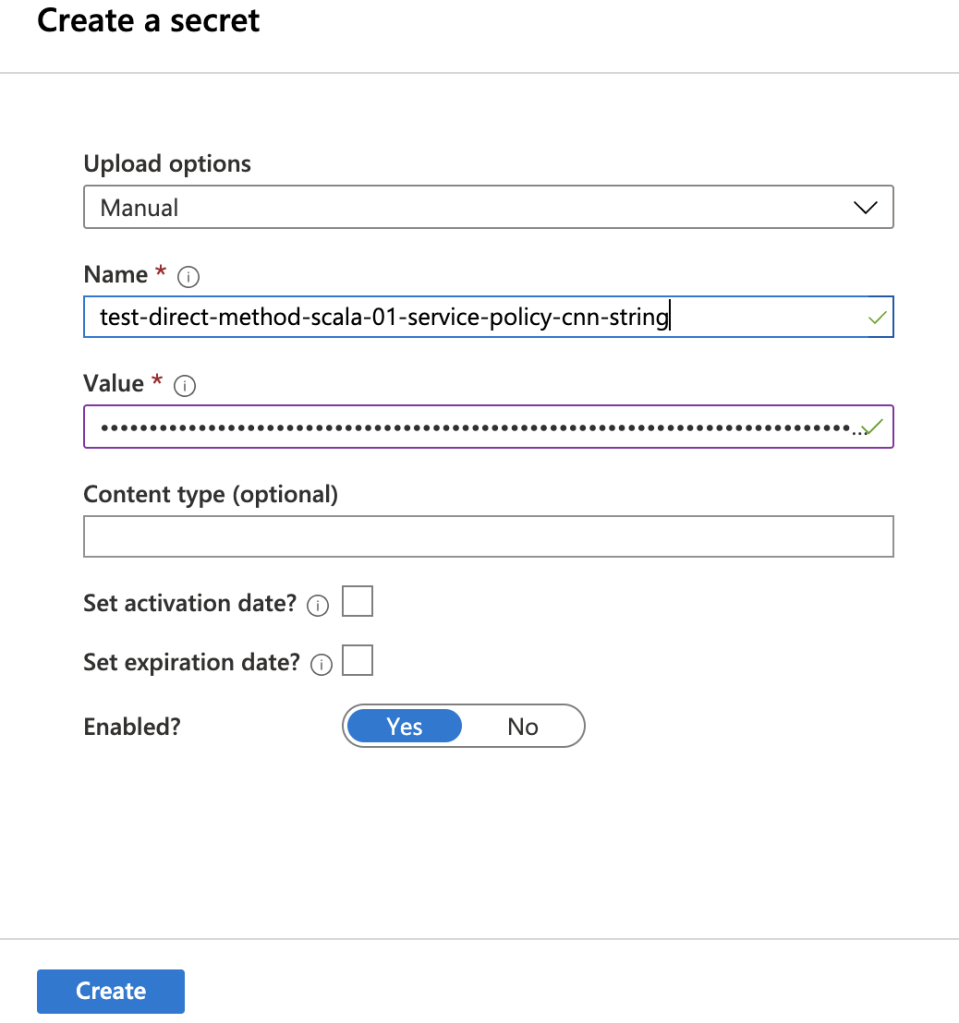
And store it in Azure Key Vault. So go ahead and create an Azure Key Vault and then:

  • Click on Secrets on the left pane and then click on Generate/Import
  • Select Manual for Upload options
  • Specify a Name such as <IOT_HUB_NAME>-service-policy-cnn-string
  • Paste the value you got from the above Azure Cli command in the Value text box

After completing the steps above and creating the secret, we will be able to use the service connection string associated with the IoT Hub in the next stages of our solution, which will be built in Databricks.

Databricks

In my opinion, the second most important factor separating Artificial Intelligence from other kinds of intelligent systems, after the complexity and type of algorithms, is the ability to process data and respond to events in real time. If the aim of AI is to replace most of human’s functionalities, the AI-powered systems must be able to mimic and replicate human brain’s ability to scan and act as events happen.

I am going to use Spark Streaming as the mechanism to process data in real time in this solution. The very first step is to set up Databricks, you can read on how to do that in my previous blog post. Don’t forget to install “azure-eventhubs-spark_2.11:2.3.6” library as instructed there. The code snippets you will see in the rest of this post are in Scala.

Load ML Model results

To be able to use the the results of our ML model, we need to load it as a Dataframe. I have the file containing the sample output saved in Azure Blob Storage. What I’ll do first is to mount that blob in DBFS:

dbutils.fs.mount(
source = "wasbs://<container-name>@<storage-account-name>.blob.core.windows.net/<directory-name(if any)>",
mountPoint = "/mnt/ml-output",
extraConfigs = Map("fs.azure.account.key.<storage-account-name>" -> "<Storage_Account_Key>"))

To get Storage_Account_Key, navigate to your storage account in Azure portal, click on Access Keys from left pane and copy the string under Key1 -> Key.

After completing above steps, we will be able to use the mount point in the rest of our notebook, which is much easier than having to refer to the storage blob every time. The next code snippet shows how we can create a Dataframe using the mount point we just created:

val CSV_FILE="/mnt/ml-output/ml_results.csv"
val mlResultsDF = sqlContext.read.format("csv")
.option("header","true")
.option("inferSchema","true")
.load(CSV_FILE)

Executing the cell above in Databricks notebook creates a DataFrame containing the fields in the sample output file:

Connect to IoT Hub and read the stream

This step is explained in my previous blog post as well, make sure you follow the steps in “Connect to IoT Hub and read the stream” section. For the reference, Below is the Scala code you would need to have in the next cell in the Databricks notebook:

import org.apache.spark.eventhubs._
import org.apache.spark.eventhubs.{ ConnectionStringBuilder, EventHubsConf, EventPosition }
import org.apache.spark.sql.functions.{ explode, split }
val connectionString = ConnectionStringBuilder("<Event hub connection string from Azure portal>").setEventHubName("<Event Hub-Compatible Name>")
.build
val eventHubsConf = EventHubsConf(connectionString)
.setStartingPosition(EventPosition.fromEndOfStream)
.setConsumerGroup("<Consumer Group>")
val sensorDataStream = spark.readStream
.format("eventhubs")
.options(eventHubsConf.toMap)
.load()

Apply structure to incoming data

Finishing previous step gives us a DataFrame containing the data we receive from our connected crane. If we run a display command on the DataFrame, we see that the data we received does not really resemble what is sent by the simulator code. That’s because the data sent by our code actually goes into the first column, body, in binary format. We need to apply appropriate schema on top of that column to be able to work with the incoming data with structured mechanism, e.g. SQL.

import org.apache.spark.sql.types._
import org.apache.spark.sql.functions._
val schema = (new StructType)
    .add("device_id", StringType)
    .add("temperature", DoubleType)
    .add("humidity", DoubleType)
    .add("height", DoubleType)
    .add("device_time",
         MapType(
          StringType,
          new StructType()
          .add("year", IntegerType)
          .add("month", IntegerType)
          .add("day", IntegerType)
          .add("hour", IntegerType)
          .add("minute", IntegerType)
          .add("second", IntegerType)
          .add("nano", IntegerType)
          )
       )
    .add("latitude", DoubleType)
    .add("longitude", DoubleType)
    .add("wind_speed", DoubleType)
    .add("load_weight", DoubleType)
    .add("lift_angle", DoubleType)
val sensorDataDF = sensorDataStream
.select(($"enqueuedTime").as("Enqueued_Time"),($"systemProperties.iothub-connection-device-id").as("Device_ID")
,(from_json($"body".cast("string"), schema).as("telemetry_json")))
.withColumn("eventTimeString", concat($"telemetry_json.device_time.date.year".cast("string"),lit("-"), $"telemetry_json.device_time.date.month".cast("string")
,lit("-"), $"telemetry_json.device_time.date.day".cast("string")
,lit(" "), $"telemetry_json.device_time.time.hour".cast("string")
,lit(":"), $"telemetry_json.device_time.time.minute".cast("string")
,lit(":"), $"telemetry_json.device_time.time.second".cast("string")
))
.withColumn("eventTime", to_timestamp($"eventTimeString"))
.select("Device_ID","telemetry_json.temperature","telemetry_json.height","telemetry_json.wind_speed","telemetry_json.load_weight","telemetry_json.lift_angle"
,"eventTimeString","eventTime")
.withWatermark("eventTime", "5 seconds")

The code above does the following:

  • Defines the schema matching the data we produce at source
  • Applies the schema on the incoming binary data
  • Extracts the fields in a structured format including the time the record was generated at source, eventTime
  • Uses the eventTime column to define watermarking to deal with late arriving records and drop data older than 5 seconds

The last point is important to notice. The solution we’re building here is to deal with changes in the environment where the crane is operating in, in real-time. This means that the solution should wait for the data sent by the crane only for a limited time, in this case 5 seconds. The idea is that the solution shouldn’t take actions based on old data, since a lot may change in the environment in 5 seconds. Therefore, it drops late records and will not consider them. Remember to change that based on the use case you’re working on.

Running display on the resulting DataFrame we get following:

display(sensorDataDF)

Decide when to take action

Now that we have both the ML model results and IoT Device data in separate DataFrames, we are ready to code the logic that defines when our solution should send a command back to the device and command it to slow down. One point that is worth noticing here is that the mlResultsDF is a static DataFrame whereas sensorDataDF is a streaming one. You can check that by running:

println(sensorDataDF.isStreaming)

Let’s go through what needs to be done at this stage one more time: as the data streams in from the crane, we need to compare it with the result of the ML model and slow it down when the incoming data falls in the range defined by the ML model. This is easy to code: all we need to do is to join the 2 datasets and check for when this rule is met:

val joinedDF = sensorDataDF
.join(mlResultsDF, $"temperature" >= $"Min_Temperature" && $"temperature" < $"Max_Temperature" && $"wind_speed" >= $"Min_Wind_Speed" && $"wind_speed" < $"Max_Wind_Speed" && $"load_weight" >= $"Min_Load_Weight" && $"load_weight" < $"Max_Load_Weight" && $"height" >= $"Min_Load_Height" && $"height" < $"Max_Load_Height" && $"lift_angle" >= $"Min_Lift_Angle" && $"lift_angle" < $"Max_Lift_Angle")

The result of running above cell in Databricks notebook would be a streaming DataFrame which contains the records our solution need to act upon.

Connect to IoT Hub where devices send data to

Now that we have worked out when our solution should react to incoming data, we can move to the next interesting part which is defining how and what of taking action on the device. We already discussed that an action is taken on the crane by calling a direct method. This method instructs crane to slow down by the percentage that is passed in as the parameter. If you look into the SimulatedDevice.java file in the azure-iot-samples-java github repo, there is a switch expression in the “call” function of “DirectMethodCallback” class which defines the code to be executed based on the different direct methods called on the IoT device. I extended that to simulate crane being slowed down, but you can work with the existing “SetTelemetryInterval” method.

So, what we need to do at this stage is to connect to the IoT Hub where the device is registered with from Databricks notebook, and then invoke the direct method URL which should be in the form of “https://{iot hub}/twins/{device id}/methods/?api-version=2018-06-30

To authenticate with IoT Hub, we need to create a SAS token in form of “SharedAccessSignature sig=<signature>&se=<expiryTime>&sr=<resourceURI>”. Remember the service level policy connection string we put in Azure Key Vault? We are going to use that to build the SAS Token. But first, we need to extract the secrets stored in Key Vault:

val vaultScope = "kv-scope-01"
var keys = dbutils.secrets.list(vaultScope)
val keysAndSecrets = collection.mutable.Map[String, String]()
for (x <- keys){ 
   val scopeKey = x.toString().substring(x.toString().indexOf("(")+1,x.toString().indexOf(")")) 
   keysAndSecrets += (scopeKey -> dbutils.secrets.get(scope = vaultScope, key = scopeKey) )
}

After running the code in above cell in Databricks notebook, we get a map of all the secrets stored in the Key Vault in form of (“Secret_Name” -> “Secret_Value”).

Next, we need a function to build the SAS token that will be accepted by IoT Hub when authenticating the requests. This function will do the followings:

  • Uses the IoT Hub name to get the service policy connection string from the Map of secrets we built previously
  • Extracts components of the retrieved connection string to build host name, resource uri and shared access key
  • Computes a Hash-based Message Authentication Code (HMAC) by using the SHA256 hash function, from the shared access key in the connection string
  • Uses an implementation of “Message Authentication Code” (MAC) algorithm to create the signature for the SAS Token
  • And finally returns SharedAccessSignature
import javax.crypto.Mac
import javax.crypto.spec.SecretKeySpec
import java.net.URLEncoder
import java.nio.charset.StandardCharsets
import java.lang.System.currentTimeMillis
val iotHubName = "test-direct-method-scala-01"
object SASToken{
   def tokenBuilder(deviceName: String):String = {
        val iotHubConnectionString = keysAndSecrets(iotHubName+"-service-policy-cnn-string")
        val hostName = iotHubConnectionString.substring(0,iotHubConnectionString.indexOf(";"))
        val resourceUri = hostName.substring(hostName.indexOf("=")+1,hostName.length)
        val targetUri = URLEncoder.encode(resourceUri, String.valueOf(StandardCharsets.UTF_8))
        val SharedAccessKey = iotHubConnectionString.substring(iotHubConnectionString.indexOf("SharedAccessKey=")+16,iotHubConnectionString.length)//iotHubConnectionStringComponents(2).split("=")
        val currentTime = currentTimeMillis()
        val expiresOnTime = (currentTime + (365*60*60*1000))/1000
        val toSign = targetUri + "\n" + expiresOnTime;
        var keyBytes = java.util.Base64.getDecoder.decode(SharedAccessKey.getBytes("UTF-8"))
        val signingKey = new SecretKeySpec(keyBytes, "HmacSHA256")
        val mac = Mac.getInstance("HmacSHA256")
        mac.init(signingKey)
        val rawHmac = mac.doFinal(toSign.getBytes("UTF-8"))
        val signature = URLEncoder.encode(
        new String(java.util.Base64.getEncoder.encode(rawHmac), "UTF-8"))
        val sharedAccessSignature = s"Authorization: SharedAccessSignature sr=test-direct-method-scala-01.azure-devices.net&sig="+signature+"&se="+expiresOnTime+"&skn=service"
        return sharedAccessSignature
   }
}

The code above is the part I am most proud of getting to work as part of this blog post. I had to go through literally several thousands of lines of Java code to figure out how Microsoft does it, and convert it to Scala. But please let me know if you can think of a better way of doing it.

Take action by invoking direct method on the device

All the work we did so far was to prepare for this moment: to be able to call a direct method on our simulated crane and slow it down based on what the ML algorithm dictates. And we need to be able to do so as records stream into our final DataFrame, joinedDF. Let’s define how we can do that.

We need to write a class that extends ForeachWrite. This class needs to implement 3 methods:

  • open: used when we need to open new connections, for example to a data store to write records to
  • process: the work to be done whenever a new record is added to the streaming DataFrame is added here
  • close: used to close the connection opened in first method, if any

We don’t need to open and therefore close any connections, so let’s check the process method line by line:

  1. Extracts device name from incoming data. If you run a display on joinedDF, you’ll see that the very first column is the device name
  2. Builds “sharedAccessSignature” bu calling SASToken.tokenBuilder and passing in the device name
  3. Builds “deviceDirectMethodUri” in ‘{iot hub}/twins/{device id}/methods/’ format
  4. Builds “cmdParams” to include the name of the method to be called, response timeout, and the payload. Payload is the adjustment percentage that will be sent to the crane
  5. Builds a curl command with the required parameters and SAS token
  6. Executes the curl command
import org.apache.spark.sql.{ForeachWriter, Row}
import java.util.ArrayList
import sys.process._
class StreamProcessor() extends ForeachWriter[Row] {
def open(partitionId: Long, epochId: Long) = {
println("Starting.. ")
true
}
def process(row: Row) = {
val deviceName = row(0).toString().slice(1,row(0).toString().length-1)
val sharedAccessSignature = SASToken.tokenBuilder(deviceName)
val deviceDirectMethodUri = "https://test-direct-method-scala-01.azure-devices.net/twins/"+deviceName+"/methods?api-version=2018-06-30"
val cmdParams = s"""{"methodName": "setHeightIncrements","responseTimeoutInSeconds": 10,"payload":"""+ row(18).toString()+"}"
val cmd = Seq("curl","-X", "POST", "-H", sharedAccessSignature, "-H","Content-Type: application/json" ,"-d", cmdParams,deviceDirectMethodUri)
cmd.!
}
def close(errorOrNull: Throwable) = {
if (errorOrNull!=null){
println(errorOrNull.toString())
}
}
}

The very last step is to call the methods we defined in the StreamProcessor class above as the records stream in from our connected crane. This is done by calling foreach sink on writeStream:

val query =
joinedDF
.writeStream
.foreach(new StreamProcessor())
.start()

And we’re done. We have solution that is able to control theoretically millions of IoT devices using only 3 services on Azure.

The next step to go from here would be to add security measures and mechanisms to our solution, as well as monitoring and alerting. Hopefully I’ll get time to do them soon.

Stream IoT sensor data from Azure IoT Hub into Databricks Delta Lake

IoT devices produce a lot of data very fast. Capturing data from all those devices, which could be at millions, and managing them is the very first step in building a successful and effective IoT platform.

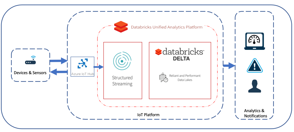
Like any other data solution, an IoT data platform could be built on-premise or on cloud. I’m a huge fan of cloud based solutions specially PaaS offerings. After doing a little bit of research I decided to go with Azure since it has the most comprehensive and easy to use set of service offerings when it comes to IoT and they are reasonably priced. In this post, I am going to show how to build the architecture displayed in the diagram below: connect your devices to Azure IoT Hub and then ingest records into Databricks Delta Lake as they stream in using Spark Streaming.

Solution Architecture

Setup Azure IoT Hub and Register a Device

The very first step is to set up Azure IoT Hub, register a device with it and test it by sending data across. This is very well explained by Microsoft here. Make sure you follow all the steps and you’re able to read the messages sent to IoT Hub at the end.

The only extra step we need to take is to add a new consumer group to the IoT Hub. Doing this means our Spark Streaming application will have its own offset, tracking where in the queue it has last read the records coming from devices. By assigning unique consumer groups to each application that subscribes to IoT Hub, we can send the record coming from IoT devices to multiple destinations, for example to store them in Blob storage, send them to Azure Stream Analytics and do real-time analytics, as well as a delta table in Databricks Delta Lake.

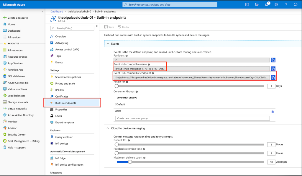
Navigate to IoT Hub page on the Azure portal and select your hub. Click on Built-in endpoints and add a new Consumer Group:

Add Consumer Group to IoT Hub

Databricks: Unified Analytics Platform & Delta Lake

Moving on to the next layer in our architecture, we’re going to set up Databricks. Databricks offers a platform that unifies data engineering, data science and business logic. It is basically PaaS offering for Spark on cloud, which speeds up data exploration and preparation.

Why Delta?

Delta Lake is a storage layer invented by Databricks to bring ACID transactions to big data workloads. This is a response to limitation within the existing big data storage mechanisms like Parquet: They are immutable. To update a record within a Parquet file, you need to re-write the whole file. With Delta, you can easily write update statements at records level. This is all we need to know about Delta file format for the purpose of what we want to build here, more about is here.

A very important result of this feature for IoT and streaming use cases is that we will be able to query the data as they arrive, instead of having to wait for a partition to be updated (re-written)

In this solution we will see how to set up Databricks, use Spark Streaming to subscribe to records coming in to Azure IoT Hub, and write them to a Delta table.

Setup Databricks

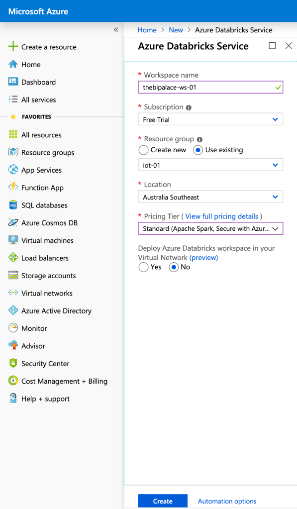
Navigate to Azure Portal and click on Create a Resource -> Analytics -> Azure Databricks. This is where you create a workspace, which is where you can access all your databricks assets. Fill up the new form that opens up and make sure you select Standard for pricing tier. Then hit Create:

Create Databricks Workspace

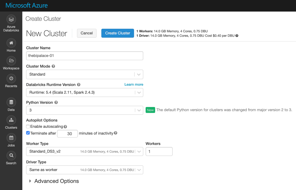
When the workspace is created, go to Azure Databricks Workspace resource page and click on Lunch Workspace. You will be navigated to your workspace. Create a new cluster with the same properties you see in the picture below. You can ask for bigger nodes or enable autoscaling, but it’s not needed for this tutorial:

Create Databricks Cluster

The next step is to create a notebook. Click on Home -> <Your Email Address> -> Create -> Notebook. Give it a name, select Scala as the default language of the notebook (you can change it later using %), and select the cluster where this notebook’s commands will run on.

Structured Streaming from IoT Hub

Create and install required Maven library

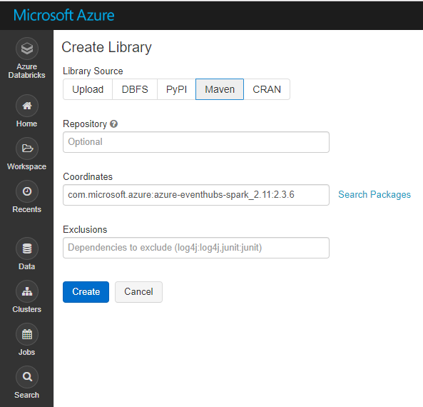
For our streaming solution to work, we need to install ” azure-eventhubs-spark_2.11:2.3.6″ Maven library. The steps to do that are very easy:

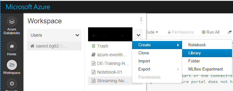
Open the notebook and click on Workspace -> [User_Name] -> Create -> Library:

Select Maven and copy and paste ” com.microsoft.azure:azure-eventhubs-spark_2.11:2.3.6″ into Coordinates box, then click on Create:

After the library is created, you’ll be redirected to the page where you can install your library on the existing clusters. Select the cluster where you’ll be running your Spark streaming code and click Install:

Important: You should restart your cluster after the installation is complete for it to take effect.

Connect to IoT Hub and read the stream

import org.apache.spark.eventhubs._
import  org.apache.spark.eventhubs.{ ConnectionStringBuilder, EventHubsConf, EventPosition }
import  org.apache.spark.sql.functions.{ explode, split }

// To connect to an Event Hub, EntityPath is required as part of the connection string.
// Here, we assume that the connection string from the Azure portal does not have the EntityPath part.
val connectionString = ConnectionStringBuilder("--IOT HUB CONNECTION STRING FROM AZURE PORTAL--")
  .setEventHubName("--IoT Hub Name--")
  .build
val eventHubsConf = EventHubsConf(connectionString)
  .setStartingPosition(EventPosition.fromEndOfStream)
  .setConsumerGroup("delta")
  
val eventhubs = spark.readStream
  .format("eventhubs")
  .options(eventHubsConf.toMap)
  .load()

The code snippet above first builds a connection string pointing to the IoT Hub we created before. The only extra steps you need to take is to get the connection string from Azure portal and replace it in ConnectionStringBuilder and then change the name in .setEventHubName to “<Event Hub-compatible name>” accordingly. Open Azure portal and go to your IoT Hub’s page. Click on Built-in endpoints and copy what you see below and paste in the code snippet in the notebook:

IoT Hub Endpoint Details

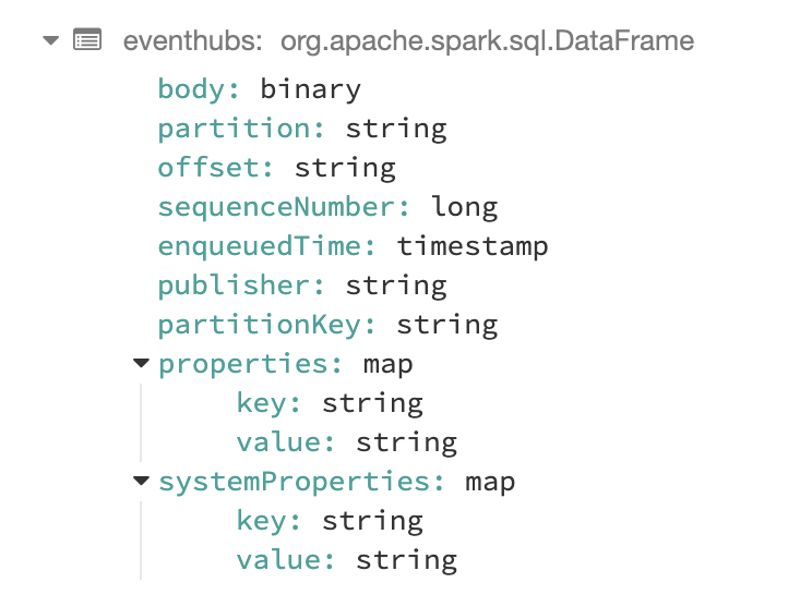
What we get after those commands are completed successfully is a DataFrame that has the following fields in it. The messages coming from our IoT device are in the “body” field:

To see how the incoming data from the IoT sensor looks like just run:

display(eventhubs)

Extract device data and create a Spark SQL Table

The next step would be to extract the device data coming in the body field of the DataFrame we built in previous step and build the DataFrame comprising of the fields we want to store in our Delta Lake to do analytics on later:

import org.apache.spark.sql.types._ 
import org.apache.spark.sql.functions._
val schema = (new StructType)
    .add("temperature", DoubleType)
    .add("humidity", DoubleType)
val df = eventhubs.select(($"enqueuedTime").as("Enqueued_Time"),($"systemProperties.iothub-connection-device-id")
                  .as("Device_ID"),(from_json($"body".cast("string"), schema)
                  .as("telemetry_json"))).select("Enqueued_Time","Device_ID", "telemetry_json.*")

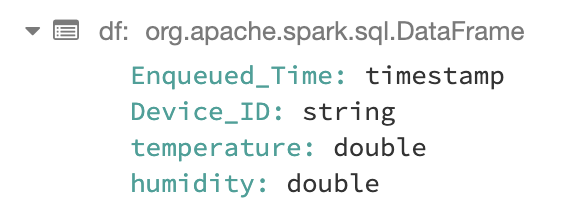
The resulting DataFrame looks like:

Now we can create a table from our DataFrame and start writing SQL commands on it:

df.createOrReplaceTempView("device_telemetry_data")

Create the final DataFrame and write stream to Delta table

We’re almost there. We have the data we receive from our IoT device in a Spark SQL table, which enables us to transform it easily with SQL commands.

Tables in a Big Data ecosystem are supposed to be partitioned. I mean they better be, otherwise they’ll cause all sorts of problems. The reason I extracted Enqueued_Time from JSON was to be able to partition my table by date/hour. IoT devices produce a lot of data and partitioning them by hour not only makes each partition reasonably sized, but also enable a certain type of analytics to be performed on the data when companies need to predict the performance of their devices at different times of the day or night, for example.

val finalDF = spark.sql("Select Date(Enqueued_Time) Date_Enqueued
, Hour(Enqueued_Time) Hour_Enqueued, Enqueued_Time, Device_ID
, temperature AS Temperature, humidity as Humidity  
from device_telemetry_data")

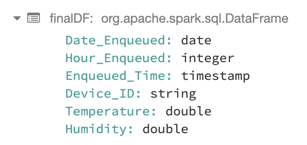
The resulting DataFrame has the following schema:

The final step is to write the stream to a Delta table:

finalDF.writeStream
  .outputMode("append")
  .option("checkpointLocation", "/delta/events/_checkpoints/etl-from-json")
  .format("delta")
  .partitionBy("Date_Enqueued", "Hour_Enqueued")
  .table("delta_telemetry_data")

Let’s check the options passed to writeStream:

  • outputMode: Specifies how the records of a streaming DataFrame are written to the streaming sink. There are 2 modes:
    • Append: Only the new records will be written to the sink
    • Complete: All records will be written to the sink every time there is an update
    • Update: Only the updated records will be outputed to sink
  • option: checkpointLocation
    • This is needed to ensure fault-tolerance. Basically we specify a location to save all application progress information. This is specially important in case of a Driver failure, read more here.
  • format: The output sink where the result will be written, obviously “delta”.
  • partitionBy: The column(s) by which we want our table to be partitioned by. We decided to partition our table hourly as explained above, so we pass in date and hour.
  • table: The name of the table.

If all the steps above have worked, you should be able to query your table and see the records inserted into the Delta table by running the following command:

%sql
SELECT * FROM delta_telemetry_data

And we’re done! Now we have a table in our Delta Lake that holds our IoT devices data. You can take it from here and do ML on the data collected or mix it with other tables you might have in your Delta Lake. And definitely feel free to ask your questions below in comments section.

Azure Databricks and CosmosDB: Tips on playing nice together

I’ve been working on a project and been using CosmosDB as a data source and extracting the data from it into Azure Databricks. Once there I apply some data and analytics magic to it. So this post is about some of the assumptions that I had about it, and some of the issues that I came across.

For setting up Databricks to get data from CosmosDB, the place to go is the Azure CosmosDB Spark connector site. I’m not going to go through installing it, as the read me and guidance on the GitHub does a good job and it is straight forward to do. There is also a tutorial here, that deals with ‘On time flight performance’, it covers how to connect, and then process data but doesn’t cover any of the issues you may have, as its using a nice, conformed data structure. In the real world, we have all sorts of weird design options, taken over the life time of a product and/or service.

I’m using the Databricks Python API to connect to CosmosDB, so the start of setting up a connection is set out here:

1234567891011cosmosConfig = {"Endpoint" : "Your endpoint here","Masterkey" : "Your key here","Database" : "Your database here","preferredRegions" : "Your region(s)","Collection" : "Your collection here","ConnectionMode": "DirectHttps","SamplingRatio" : "1.0","schema_samplesize" : "2000","query_pagesize" : "2147483647"}

Just add your keys etc, everything is nice and straight forward so far. I’ve left out the custom query option for the time being, but I’ll be coming back to it in a bit. The next bit sets up the read format by using the configuration used above, the creates a temp view called in this case “c”.

12345# Sets up the CosmosDB connection.# Creates a temp table call c, which is used in the query# to define the collectioncosmosdbConnection = spark.read.format("com.microsoft.azure.cosmosdb.spark").options(**cosmosConfig).load()cosmosdbConnection.createOrReplaceTempView("c")

SQL Queries

So now we have created a temp view in Databricks called “c” that sits over CosmosDB, we can create a data frame based on a spark SQL context query. So lets send a Cosmos SQL API style query from Databricks, for example:

12family = spark.sql(SELECT {"Name":c.id, "City":c.address.city} AS FamilyFROM c WHERE c.address.city = c.address.state)

It should return a error. Why? This was my first mistake, you can’t use the Cosmos SQL API syntax. It will not return a document, but columns and rows like a standard SQL table.

12family = spark.sql(SELECT c.id AS Name, c.city AS City FROM cWHERE c.city = c.state)

The above will work, but it will return a table like object, not a document like the CosmosDB SQL query.

Tip 1: You can’t use your Cosmos DB SQL queries, they will have to be redone in a more standard SQL syntax, but that is good, we can finally use a “Group by” to query data on CosmosDB!

CosmosDB Document Considerations

One of the issues I came across, was that we have a number of documents in our Cosmos DB, that are split by types, using an “entity” field, so we have for example, Customer and Project documents.

Now if you have the same field name in the documents, but different data types it can get mixed up? How, using this example for “customer”

1234{   #some other customer JSON here"range":"PWAQ-100","entity":"customer"}

So in this case “range” is a string.

And this for “project”:

1234{ #some other project JSON here"range":[ { "name": "Small Project", "min": 0, "max": 99 }, { "name": "Big Project", "min": 100, "max": 199 }], "entity":"project" }

So in this case “range” is an array.

Now when I do a query like the following

1test_df = spark.sql(SELECT c.range AS Range FROM c WHERE c.entity = "project")

It returns that data as a string like this:

[{name=Small Project, min=0, max=99},{name=Big Project, min=100, max=199}]

This removes the ” and changes the “:” to “=” rather than a column that contains the array which I can then explode the JSON into other objects. So I get a string back…Weird! Well what happened?  Well it’s all down in part to the configuration we set up earlier:

1"schema_samplesize" : "2000"

The first 2000 documents it read to determine the “c” table schema were of the “customer” type and set it as a string. In fact if you do the following query:

1test_df = spark.sql(SELECT * FROM c)

It will show all the columns for the Customer and Project as one big table, with all repeated columns names and datatypes that have been adjusted to fit the data frames expected schema.

There are three ways to solve this.

  1. Don’t mix datatypes for fields that have same name in your document schema
  2. Don’t store a mixture of document schemas in your CosmosDB database
  3. Use the custom query option

Using Custom Query

If like me you can’t do 1 or 2, you have to use the custom query option. Lets go back to our set up of the connection:

123456789101112cosmosConfig = {"Endpoint" : "https://cloudsuite-test.documents.azure.com:443/","Masterkey" : "wxElqnT67i3Ey7Mmh7rH2Opxxwjbn22g6RL8LFjboDK6Cqg6M8COfVcQXaJO3pxLq0vEDayidnisn5QmbN5dPQ==","Database" : "cbi_survey","preferredRegions" : "UK South","Collection" : "cbi","ConnectionMode": "DirectHttps","SamplingRatio" : "1.0","schema_samplesize" : "20000","query_pagesize" : "2147483647","query_custom" : "SELECT c.* FROM c WHERE c.entity = 'project'"}

So we have now added the following line to the config:

“query_custom” : “SELECT c.* FROM c WHERE c.entity = ‘project’”

So we now know that we will only get documents back of the  schema “project” and should map the datatypes correctly.

12345# Sets up the CosmosDB connection.# Creates a temp table call c, which is used in the query# to define the collectioncosmosdbConnection = spark.read.format("com.microsoft.azure.cosmosdb.spark").options(**cosmosConfig).load()cosmosdbConnection.createOrReplaceTempView("project")

I’ve also now create a distinct temp view called ‘project’ that I can query. I will do the same for ‘customer’ and any other document schemas stored in Cosmos DB.

Tip 2: Make sure to declare your temp views based on the documents you need

With CosmosDB and Databricks when you create the connection and query, it is schema on read. So it you have added items to your JSON structure, make sure that you set your schema sample size to allow it to read enough items, otherwise a column(s) that is in later version of your document schema, may not read correctly and any SQL queries will fail when you reference that column.

Tip 3: “schema_samplesize” should be adjusted were needed

Now I’ve wrapped up the connection and table details into a function that I can call with my entity value, and it will set that temp view up nice and cleanly.

Overall the Azure Spark Connector is works well and pulling data from Cosmos is fast. Databricks and JSON is a lot easier to handle than querying it in SQL Server, and we have been using it more for some projects for our ETL pipelines.

On the down side, the GitHub site needs a little bit of an update as it has a number of broken links, and a number of open issues that haven’t been looked at or assigned.